Year: 2010
Visiting Mexico City’s Newest Metro Tunnel: How the Country’s Capital is Upgrading its Aging Infrastructure
I was lucky enough to visit the jobsite of the Mexico City Metro Line 12 tunnel in October, along with Tunnels & Tunnelling International’s features editor Nicole Robinson. The country’s largest TBM, a 10.2 m (33.5 ft) diameter Robbins EPB, is excavating Mexico’s first new rail route in 10 years, below southern areas of the city. The 7.7 km (4.8 mi) long Mexico City Metro Line 12 is being excavated just 7 m (23 ft) below downtown areas in mixed ground including watery clay and boulders up to 800 mm (32 in) in diameter. The project is one of two major tunnels being constructed in Mexico City, the other being the 62 km (39 mi) long Emisor Oriente wastewater project, using six TBMs including three 8.93 m (29.3 ft) diameter Robbins EPBs.
During our visit to the site, the machine was between its first and second cut and cover station sites (it will hole through into seven such sites during the course of tunneling). We walked through the tunnel to view the machine, and later sat down with metro director Enrique Horcasitas of the Mexican Federal District for an interview on the current state of tunneling in Mexico.
Interview with Metro Director Enrique Horcasitas

Q: Were other methods besides tunneling with an EPB TBM considered for this tunnel?
A: Originally, the line was envisioned to be constructed using a technique of slurry walls cast in place. Most of Mexico City’s underground lines were built using this method. However, opening and closing city streets was not possible for a large portion of this route, while open cutting would interfere with existing municipal facilities and fragile archeological sites. In addition, cost estimates placed open cut excavation of the entire 24 km (15 mi) line at 19.5 billion pesos (USD $1.57 billion).
Our engineers needed a solution that would reduce risks and adverse impacts to traffic flow, as well as reduce project cost. For several weeks, methods were studied, and it was ultimately determined that a solution using multiple methods would work best. The 7.7 km (4.8 mi) long tunnel between Mexicaltzingo and Mixcoac would be excavated using a mixed ground EPB TBM, while the rest of the line between Atatonilco and Tláhuac, in much more difficult ground, would be constructed on the surface. Smaller portions of the tunnel would be constructed using cut and cover methods. The overall plan has a budget of 17.58 billion pesos (USD $1.41 billion).
Q: What does the city forecast for future ridership?
A: In the short term, it is expected this project will meet an average demand of 437,000 users per weekday. By 2030, this number is expected to grow to 600,000 users.
Q: How was the route of this line determined?
A: There is a long history associated with Mexico City’s metro plan. Engineers used to think it was impossible to excavate underground, given Mexico City’s highly complex geology. But in the 1950s and 60s, crews hand-mined the city’s main wastewater line, Emisor Central, about 100 m (330 ft) below ground. After the encouraging results, about 41 years ago, the project’s current contractor ICA (Ingenieros Civiles Asociados) began to make feasibility studies about metro lines running through the city. ICA was contracted to excavate the capital’s first metro lines, and 10 years later ICA gave the Federal District a gift: A master plan with over 300 km (185 mi) of rail that would serve as our template for decades to come.
The master plan is reviewed every 10 years, and it was most recently determined to build Line 12. The alignment is almost entirely true to the master plan, though it was made a bit longer after being reviewed by advisors, to match public demand for transportation.
Q: Are there any other metro expansions that the city is considering?
A: We are looking at doing an extension of the new Line 12, depending on the available budget. This extension would include 1,400 m (4,600 ft) of tunnels west of Mixcoac.
The next line we are considering in the master plan is Line 15, which would run directly below Insurgentes, the longest avenue in the world (18.8 km/11.7 mi), which goes straight through the city. A metro is absolutely needed on this route, as there are currently about 10,000 people per hour riding on just buses alone in each direction.
Q: Do you think current opinion about TBMs is changing in Mexico? What is the current climate towards TBMs?
A: I think the public can see the success of this tunnel—we arrived into the first station with precision, only 1 cm (0.4 in) to the side. We are monitoring settlement, and have detected only about 2 cm (0.8 in) at maximum—well within the limits and not enough to affect buildings. The public voted on where to excavate the next new line, they decided where to go, and so there is a consensus in society. I think that is why there has been a high degree of acceptance.
The operation of TBMs is seen as more favorable than hand mining or open cut, because there is less inconvenience at the surface, and building the tunnel itself is safer. For this reason, I think TBM tunneling will continue to increase in Mexico.
With the six TBMs currently excavating or being readied to excavate the new Emisor Oriente wastewater line, we now have seven TBMs operating in the country—this has never happened before. I think this is a tunneling boom!
Sub-Sea TBM Tunneling: A New Approach to Oil and Gas Production
Offshore oil production is an important sector of business worldwide, but recent events have highlighted its inherent risks. We have witnessed catastrophic accidents on offshore drilling platforms that damaged the delicate marine environment and hurt businesses and families. Inclement weather and technological unreliability compound the problems that come with accessing oil fields in deep water.
Making offshore oil drilling as safe as possible is a high priority task—and one that could be advanced through TBM tunneling. Building oil production facilities in controlled environments underground has the potential to take at least some of the variables out of the equation. The tunnels would provide human access to the well head in deep water, and could be monitored for leaks and other malfunctions.
Extensive sub-sea tunnels for this purpose are being investigated in Norway, where schematics were drawn up for tunnel access to offshore oil fields in the early 1980s. Personnel access, transportation of drilling equipment, exploration and drilling for oil, and eventual piping of oil to the shore are all performed in tunnels and caverns underground. This enables access to the drilling sites and intervention by humans, rather than by remotely controlled and operated machines thousands of feet below water. Some concepts, such as the one below, feature a triple cross section—one tunnel would be used for materials transport, one is used for transport of personnel, and the third would be used as the oil supply pipeline.
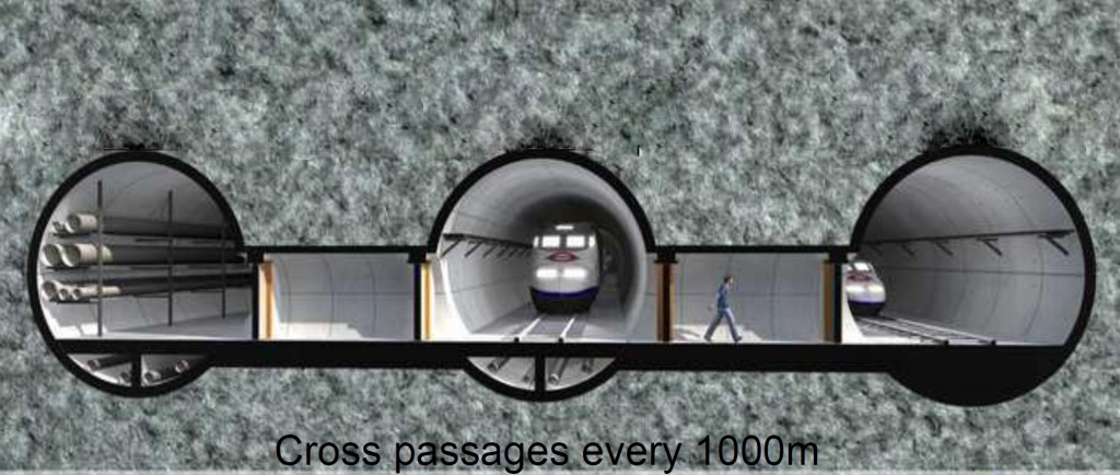
Schematic of triple cross section of concept subsea tunnel, courtesy of the Norwegian Tunnelling Society (NFF)
More than 40 subsea tunnels have been completed in Norway since their excavation was first proposed: 25 road tunnels, 8 oil pipeline tunnels, and 8 water supply tunnels. All of these tunnels were excavated by conventional drill & blast methods (D&B). The longest tunnel was 7.9 km (4.9 mi) (Bømlafjord), and the deepest is 287 m (942 ft) below sea level (Eiksund). Most of the tunnels were excavated in hard gneiss rock, with a few in shale and sandstone.
The slow relative excavation rates of drill and blast excavation, however, make this method of excavation on long sub-sea tunnels impracticable. Many new underground oil fields up for development will require long subsea tunnels of up to 50 km (31 mi) in length. These long tunnels must be excavated in the shortest possible time and as inexpensively as possible to make economical sense. At these tunnel lengths, mechanical full-face tunneling is the most realistic option. TBM technology for seabed excavation has been used on multiple projects since the 1980s, from the Channel Tunnel to the Boston Harbor Outfall and multiple tunnels worldwide.
New tunnels, as in the schematic below, would be built far below the sea bed, out of unstable regions that might experience sea water infiltration.
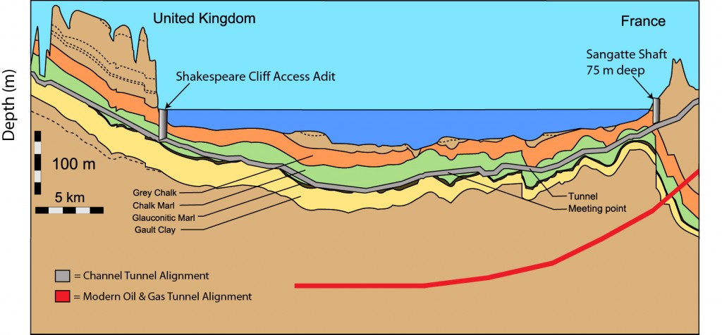
Schematic showing the depth of a modern oil and gas tunnel, compared to the depth of the Channel Tunnel.
In addition TBM tunneling would control the amount of over-break compared to drill and blast, by limiting the amount of material removed from the tunnel.
With today’s experience and know-how it is possible to excavate long tunnels under the sea in good time and with reasonable cost. The technology exists to improve oil and natural gas production from offshore oil fields, all that remains is for the method to gain acceptance in the industry.
Hybrid TBMs: A Clear Solution for Mixed Ground
It has been argued that the majority of good ground for tunneling in the world already has a tunnel going through it. While this might be an overstatement, it is true that more and more of today’s tunneling projects are being proposed in difficult, mixed ground conditions. Hybrid TBMs, specifically EPB/Slurry and EPB/Hard Rock machines, are increasingly becoming the best solution for these challenging conditions.
Hybrid machines have the potential to lower risk and make difficult excavations possible, as long as accurate geologic information is available. For example, a hybrid EPB/Open-Type machine can be optimized towards either end of the scale—depending on whether the majority of the drive is in soft soils or majority in hard rock—to produce the fastest possible advance rate over the entire project. If the tunnel is 80% soft ground and 20% hard rock, the overall machine design will be optimized towards EPB.
But what happens when the divisions are not so clear cut, or when the geology is 50% rock and 50% soft ground? A real example is the upcoming Sleemanabad Carrier Canal project, which will utilize a 10.0 m (32.8 ft) diameter Hybrid EPB/Hard Rock TBM. The 12 km (7.5 mi) long water transfer tunnel in Madhya Pradesh, India consists of shorts sections of hard rock and soft ground. Geology includes clay, gravel, marble, and hard rock up to 180 MPa (26,000 psi) UCS.
The solution at Sleemanabad is to provide three modes of tunneling: pressurized EPB tunneling, non-pressurized EPB tunneling, and open hard rock tunneling. The first half of the tunnel will be excavated using a specially designed screw conveyor, which can operate well in both the pressurized and non-pressurized environments. The oversized screw can be rotated faster to handle short sections of hard rock while minimizing any loss in efficiency.
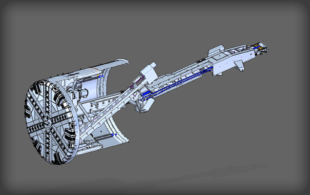
The 10.0 m (32.8 ft) diameter Hybrid EPB/Open-Type TBM for the Sleemanabad tunnel. The screw conveyor can be switched out with the TBM belt conveyor.
When a longer section of rock is encountered, the screw conveyor is removed and switched out for the TBM belt conveyor. Additional welded steel is added to the cutterhead to close up the open soft ground design, and the machine operates as a Single Shield TBM.
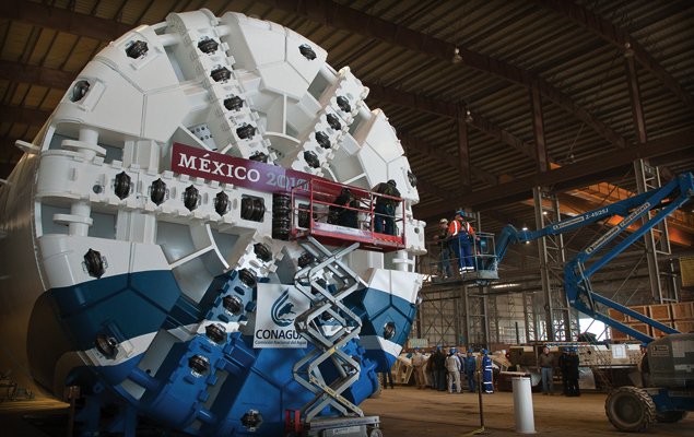
The mixed ground cutterhead supplied for one of three Robbins EPBs that will excavate Mexico’s Emisor Oriente tunnels is nearly identical to the one designed for the Sleemanabad tunnel.
In other conditions, such as sections of soft ground and rock mixed with sections of high water content, a Hybrid Slurry/EPB Type machine is desirable. The machines can similarly be optimized towards slurry or EPB depending on the amount of groundwater expected. An interesting example of this type of hybridization took place at the South Central Hillsborough Intertie Tunnel in Tampa Bay, Florida, USA. The machine excavated limestone with significant groundwater using both a screw conveyor and modified slurry removal system. See the case study here.
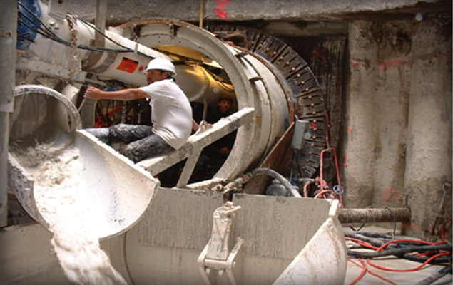
The Robbins hybrid EPB/Slurry machine at Tampa Bay utilized both a screw conveyor and modified slurry muck removal.
Hybrid machines are becoming more common, and are likely to gain in popularity over the near future. With greater experience will also come greater optimization of conversion times between modes—one of the biggest challenges during tunneling. While these machines do have some negatives, as all machine types do, the solution of Hybrid TBMs in mixed ground vastly outweighs any difficulties over the life of the project.
Ground Control: Mitigating the Inherent Risks of Urban Tunneling
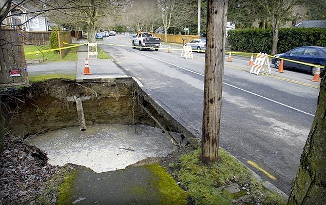
Sinkholes, as seen here at the Brightwater Conveyance Tunnels, can be an unfortunate end result of settlement. Photo Credit: TunnelTalk.com
Settlement. It is one of the biggest risks in urban tunneling and the cause of sinkholes, cracked building foundations, and tunnel collapses. Surface subsidence and upheaval have vexed contractors and equipment suppliers worldwide, but there are some proven ways to minimize ground movement, even in low cover tunnels.
Tunneling at Mexico City Metro’s Line 12 provides a good, recent example of settlement prevention. The 7.7 km (4.8 mi) route is being excavated just 7.5 to 14 m (25 to 45 ft) below downtown Mexico City. The 10.2 m (33.5 ft) diameter Robbins EPB is surfacing into eight cut and cover station sites during excavation, all along major downtown streets.
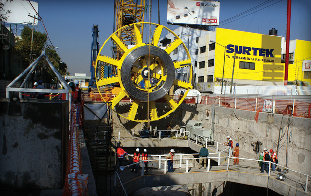
The Robbins EPB is boring just 7.5 to 14 m (25 to 45 ft) below city streets. Photo Credit: Yazmin Reyes
The ground, which consists of watery clays, sand, and large boulders up to 800 mm (2.5 ft) in diameter, makes settlement a concern. Ismail Benamar, Tunnel Manager for contractor Ingenieros Civiles Asociados (ICA), spoke about the measures they are taking to control the ground: “We have an extensive monitoring program to detect displacements and pore pressure on the surface, underground, inside the tunnel, and in the most critical structures next to the tunneling line.” The risk of surface subsidence and vibration is also being controlled by regulating the rate of advance and controlling earth pressure at the front of the machine, as well as the back-fill grouting pressure.
In particularly low cover areas, Benamar cited a reduction in EPB cutterhead rotation as one of the primary means of avoiding ground disturbance. Cutterhead rotation is kept low (around 1.5 RPM) while torque is kept relatively high.
In addition, the machine’s two-component back-filling system is used to further stabilize the space between concrete segments and bored tunnel. The liquid mixture consists of water and bentonite cement plus an accelerant, which are combined in the tail shield and harden rapidly after injection. Because the two liquids are kept separate, high pressure concrete pumps, which can disrupt the surrounding geology, are not needed.
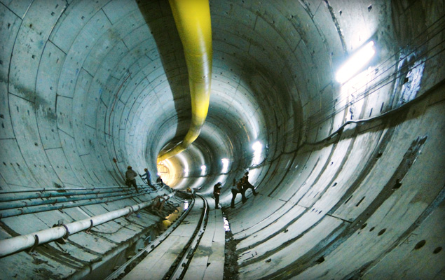
The Robbins EPB is utilizing two-component back-filling behind segments as one way of minimizing settlement. Photo Credit: Yazmin Reyes
By May 21, 2010, the machine had broken through into Mexicaltzingo Station—the first of eight cut and cover station sites along the tunnel route. Little to no settlement issues were recorded during tunneling.
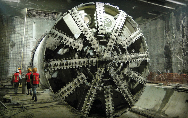
The Robbins EPB broke through into an intermediate station in May 2010. Photo Credit: Yazmin Reyes
Taken together, the methods at Mexico City Metro show the best ways to minimize settlement in urban EPB tunneling. Settlement can be due to multiple factors, including over-excavation, improper ground conditioning, inadequate back-filling, or loss of face pressure. Despite the risks, proper machine design, continuous monitoring, and a knowledgeable crew can keep ground under control.
For more about the causes of settlement and tunnel collapse, visit an online forum at tunneltalk.com
Multiple Machines: The Challenges and Successes of Delivering Three TBMs for Malaysia’s Longest Water Tunnel
Simultaneous delivery of TBMs, some of the most complex machines in the construction industry, is no easy task. Robbins TBM assembly is most often a local process—one that requires skilled workers with knowledge of components designed and manufactured all over the world.
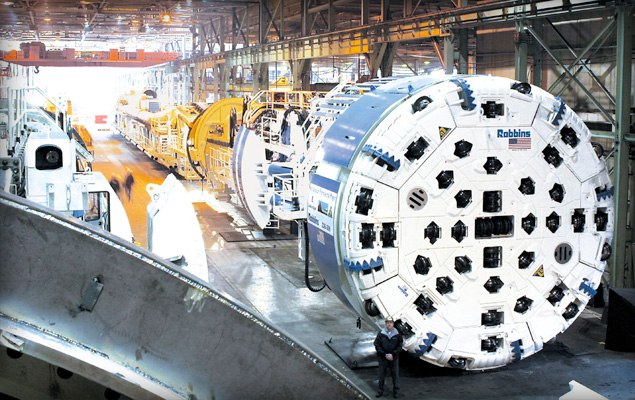
Robbins Main Beam TBMs assembled in the U.S. manufacturing facility.
Robbins use of local or nearby shops can often cut down on delivery times. A partial video of the TBM assembly process in the Robbins China-Shanghai facility is available here:
The video depicts the recent assembly of one of three 5.2 m (17.2 ft) diameter Robbins Main Beam TBMs. The machines are being built simultaneously for Malaysia’s Pahang Selangor Raw Water Tunnels, and are a good example of the assembly process.
Each machine is built at a workshop in Shanghai from components manufactured in the U.S. and China. After assembly of each machine is complete, the TBM and continuous conveyor system are shipped from Shanghai to Port Kelang in Malaysia. Once at the port, the components are trucked to the jobsite.
“One of the most difficult processes is finding a single shop that can manage the volume of fabrications and machining. The delivery times for the Malaysian TBMs are one month apart, which means that at one point you are disassembling and shipping the first machine, testing the second machine and starting assembly of the third machine,” said Kolenich. On average, each TBM requires a skilled crew of 20-30 fabricators, welders, and technicians, but shorter delivery schedules can require up to 60 people in two shifts. “We have an experienced group in China that has been building machines for many years,” he added.
Assembly of TBM #3, the first machine to be built, was completed in early July 2010. Assembly of the machine began with core components, including the main bearing and back-up structures, and finished with installation of the electrical and hydraulics systems, as well as outer components including cutterhead pieces and ground support.
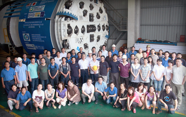
The first of three Robbins Main Beam TBMs was completed in July 2010.
“We perform all of the same quality inspections in our shops, regardless of location,” adds Kolenich. “At the end of assembly there is a two to three week no-load testing period to ensure that each machine is set up and functioning properly per the contractual and engineering requirements.”
The two other Robbins Main Beams will be completed later in 2010, with the factory acceptance for TBM #1 scheduled in August and TBM #2 in mid-September. The three machines will be launched between December of 2010 and March 2011.
For more about the Pahang Selangor Raw Water Transfer tunnels, visit the Malaysian Government’s Ministry of Energy, Green Technology, and Water.
View a short video about the project here:
Ground Support for High Cover Tunnels: What is the Best Method?
Conditions in high cover tunnels are often challenging. At the Olmos Trans-Andean tunnel, crews face 2,000 m (6,500 ft) of hard quartz porphyry, andesite, and other volcanic rocks under high stress. At two rail tunnels in China’s Gansu Province, open-type machines are boring beneath 1,400 m (4600 ft) of weak phyllite and sandstone.
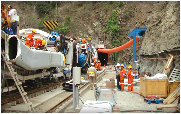
Launch of the Robbins TBM at Peru’s Olmos project, the world’s second deepest tunnel
Ground support, particularly in deep tunnel projects, is a highly debated topic. However, recent successes have pointed to several systems that work in a variety of situations. The Robbins Main Beam at Olmos was launched in 2007, and began to experience significant rock bursting and cathedralling under sections of high cover. “We encountered a 1,200 m (4,000 ft) section of highly fractured ground, with over 8,500 recorded rock bursts. Cavities also formed during tunneling that had to be injected with grout,” said John Simm, Robbins Field Service Superintendent.
To better contain the fractured rock, the machine’s roof shield fingers were removed and replaced with the McNally Support System, supplied by C&M McNally Engineering of Toronto, Ontario, Canada. The McNally support System provides the benefit of continuous support along the roof area of the tunnel, which protects workers from falling rock. The system works by replacing the curved finger shield plate for a curved assembly of pockets with rectangular cross-sections. Steel or wood slats are extruded from the pockets and bolted to the tunnel crown using a steel strap, effectively supporting and minimizing collapsing ground. As the machine advances, slats are reloaded into the pockets.
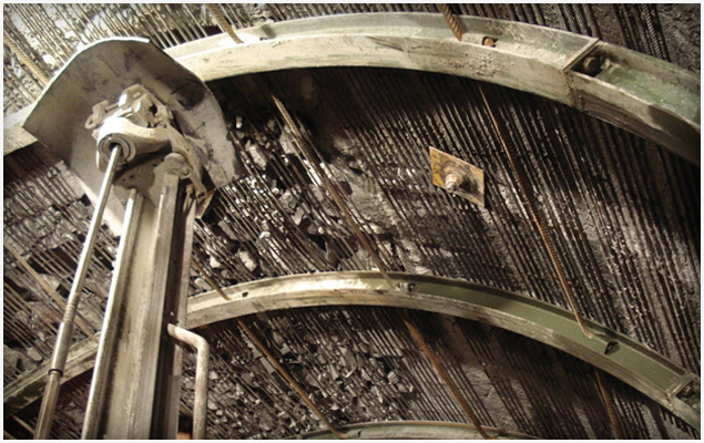
McNally slats supporting rock in the Olmos Trans-Andean Tunnel
The below video shows the crew loading McNally slats into the pockets:
The system successfully contained numerous high-pressure rock bursts at Olmos, as seen in the below video courtesy of Dean Brox from Hatch Mott MacDonald:
For the machines at China’s West Qinling tunnels, the answer is a versatile ground support system that can be adapted depending on the ground conditions. The two 10.2 m (33.5 ft) diameter Main Beam TBMs are the first Robbins Main Beam machines built with specialized ground support and no finger shields. Instead of the roof fingers, the machines are designed with mesh pockets beneath a protective shield for workers to safely install mesh panels.
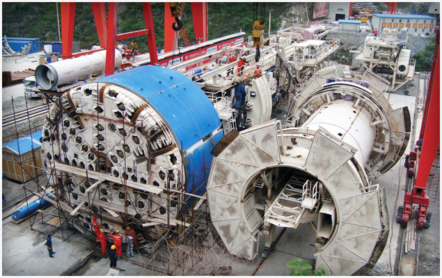
Assembly of two Robbins Main Beams with specialized ground support at China’s West Qinling Tunnels
The machines can also use the McNally Support System if needed. Modified pockets can be bolted inside the mesh windows, allowing space for short slats of steel or wood.
In addition, streamlined materials handling and separate roof and probe drills allow for improved progress in high cover conditions. Redesigned ring beam installers allow for loose assembly and expansion against the tunnel walls, and can be easily converted to install steel straps rather than full rings.
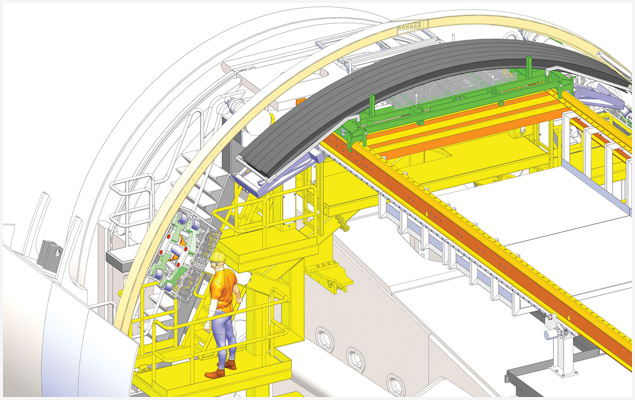
Materials including ring beams and mesh panels are transported on a remotely operated carriage, requiring fewer transfer points
Both machines are currently excavating 16.6 km (10.3 mi) long rail tunnels.
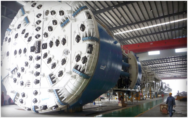
The two 10.2 m (33.5 ft) TBMs were launched in June and July 2010
For more information on ground support in large diameter tunnels, check out this recent technical paper: Large Diameter TBMs_WTC2010
Robbins EPB TBM Cutterheads
This video describes custom cutterhead design for Robbins soft ground tunnel boring machines, known as Earth Pressure Balance Machines.
Continuous Conveyor Design in EPB TBM Applications
While continuous conveyors have become the muck removal system of choice in long, hard rock TBM tunnels, they have gained acceptance in soft ground tunnels only recently. Soft ground, EPB TBM-driven tunnels provide a challenging environment for continuous conveyors due to the variety of materials present. The design of both horizontal and vertical soft ground conveyors will vary depending on the types of excavated material, amount of water present, and other factors. This paper will address the challenges of effective conveyance in different ground materials by analyzing conveyor performance in several recent EPB TBM projects.
Urban EPB Tunneling in Limited Space: A Case Study of the San Francisco Central Subway Project
The San Francisco Central Subway project is a challenging modern example of urban tunneling in limited space conditions. Two 6.3 m diameter Earth Pressure Balance Machines (EPBs) are excavating parallel 2.5 km long tunnels under low cover and in mixed ground conditions. The small launch site situated between an interstate and an off-ramp, highly curved tunnel alignment, and geology are particular challenges. These elements required customized tunnel and machine design, from TBM shipment and assembly, to launch and excavation.
This paper discusses the project challenges and solutions at the Central Subway project, with a focus on TBM and continuous conveyor logistics. Requirements of the project include explosion-proof electrical components, laser-guided survey, rubber-tired supply vehicles, and machine and back-up solutions for steep inclines and tight curves.
Recent Posts
- Long Haul TBM: Use of a Rebuilt Main Beam Machine at the DigIndy Tunnel System in Indianapolis, IN
- Evaluating TBM Design and Performance, 30 Years Apart: The Lesotho Highlands Water Tunnel, Phase 1 and Phase 2
- Use of a Tunnel Boring Machine on Nepal’s First and Second TBM-Driven Tunnels
- Record-Setting Large Diameter Mixed Ground Tunneling in Turkey: The Eşme-Salihli Railway Tunnel
- Lessons Learned During Excavation of the Incredibly Challenging Yin Han Ji Wei Water Diversion Tunnel

 Close
Close  Menu
Menu 


