Category: Redefining the Industry
Onsite First Time Assembly Works: Debunking the Most Common Myths
I have to admit, that the first time I gave much thought to Onsite First Time Assembly (OFTA) for new machines was following a dinner conversation with a very experienced engineer from one of the large Italian underground contractors. The engineer suggested that it was his opinion that on large diameter machines, perhaps above 8 m or so, that much time and money could be saved by an OFTA program, which would allow the machine to be initially assembled on location. He said he did not believe the huge amount of labor expended to completely assemble a TBM in the shop, which then had to be repeated in the field, could be justified. He argued that labor was being duplicated and the result was a longer delivery period that was reasonably required. This conversation, taking place in the mid-nineties, is what first triggered my thinking on the subject. Well, that conversation and couple of glasses of Brunello di Montalcino! My engineering friend raised a very valid point and I’ve given the subject much thought since, and discussed OFTA with many people in the industry. It appears to me that, even though the method has been successfully used on many of our projects worldwide, there are a few “myths” that have gained traction regarding the risks of OFTA. I’ll address two of these OFTA myths.
Myth No. 1 – It will be a disaster if the parts don’t fit together on the job site! That is why a full factory assembly is required.
This myth doesn’t take into account three factors:
1. Partial assembly: Major sub-assemblies are pre-assembled in the factory. The main bearing and seal assembly, for example, is fully factory assembled. It is only the major parts that may not be pre-assembled. However, in many cases, we pre-fit the pieces; forward shield to outer telescopic shield, outer to inner telescopic, inner telescopic to gripper shield, and so on for a double shield machine. So the part fit-up is checked but the entire machine is not put together in the factory.
2. Modern measurement devices: In those cases where it is not possible to pre-fit two pieces in the factory, we can use modern Coordinate Measuring Machines (CMMs) or “Laser Trackers” to take precise measurements of both pieces to insure fit up when they meet in the field.
3. In-field repairs: When an offshore oil rig has a component failure do they disassemble it and take it to the mainland for repairs? When repairs are required on hydroelectric turbines and generators, do they always take the big parts to a machine shop to repair? No, they do not. Many repairs of large scale equipment are made in situ, wherever the plant is located. If it is discovered at the job site that a component has been mis-machined / manufactured it is most likely a minor error (remember the CMM measurements and component fit-ups in factory partial assembly) and repair can be effected on the piece in place at the job site. In Robbins experience, this has always been the case and such repairs have been carried out when discovered on site and without impact to final startup schedule.
Myth No. 2 – The labor cost on an underground job site is far higher than labor cost in a factory. It will cost far more money and time to assemble the machine on site for the first time.
OFTA Myth No. 2 leads to a wrong conclusion regarding cost, and fails to examine fully the potential benefits.
1. Cost: This above statement is generally true; however, it does not necessarily follow from this statement that money will be saved by having a factory assembly plus a job site assembly. Robbins history with in-factory and OFTA assembly reveals the following:
Traditional Factory Assembly
- Full factory assembly hours: X hours
- On-site assembly of a fully factory assembled machine: 0.5X hours
OFTA Method
- Partial factory assembly for OFTA delivery: 0.5X hours
- OFTA site assembly of a partial factory assembled machine: 0.7X hours
Where the value of X is dependent upon the size and type of TBM as well as the complexity of the backup system.
If we assume that the cost of labor on the job site is twice the cost in the factory, then we can use $100/ hour for the job site and $50 / hour for the factory. The total cost for the two methods is then:
- Traditional method cost = X hours ($50/hour) + 0.5X hours ($100/hour) = $100X
- OFTA method cost = 0.5X hours ($50/hour) + 0.7X hours ($100/hour) = $95X
In short, the total costs are nearly the same, or perhaps with some savings in favor of the OFTA method.
2. Schedule: Another flaw with Myth No. 2 is that it does not consider a large potential benefit: the savings in schedule possible with the OFTA method. By not completely assembling the TBM in the factory, it is possible to deliver a working TBM at the job site one to two and a half months earlier than with a traditional full-factory assembly and delivery. This is a significant savings for most projects, when the site assembly can be done at this early stage.
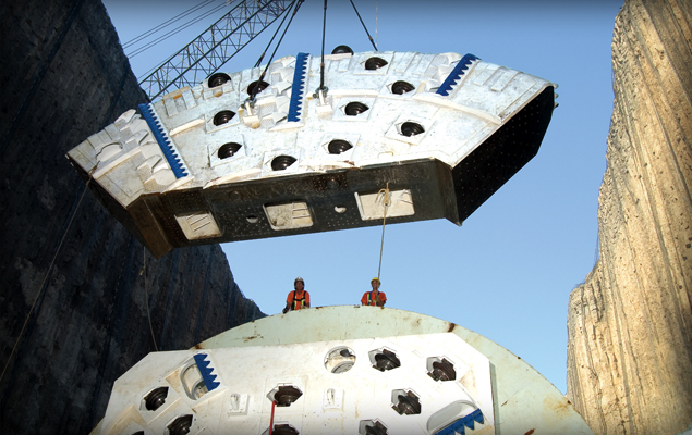
OFTA for the 14.4 m diameter Niagara TBM was completed in four months, saving an estimated four to five months on the delivery schedule.
3. Training of site personnel: Another potential benefit that Myth No. 2 does not address is that of training. The contractor’s site personnel who are involved with OFTA assembly and testing get far more training due to the additional hours spent on the assembly and testing, and the larger Robbins crew present to assist and advise. Robbins’ experience indicates that contractors who opt for OFTA deliveries are frequently capable of taking over the full operation and maintenance of their new TBM much quicker than contractors who opt for a traditional delivery. This is due to the much deeper knowledge the contractor’s personnel gain during the OFTA assembly and testing.
In summary, the question to be asked when making the decision to use OFTA or go for a traditional factory assembly is: What are the potential risks and what are the potential rewards? One must examine all potentials of the OFTA scenario, pros and cons, to come to the correct solution. I’m not claiming that an OFTA scenario is correct for every project. For example, if the start of boring of the tunnel is not on the critical path for the project and the TBM is a smaller diameter unit, it might be advisable to allow a full factory assembly. That way, when the job site is finally ready for the machine, it can be assembled a bit quicker on site. Again, if the start of boring is not on the critical path and the labor cost difference between job site and factory is larger (e.g., job site is in Finland, TBM factory is in China), then it could be that a full factory assembly can be justified on a cost only basis. However, in nearly every case when the start of boring the tunnel is on the critical path, then the faster delivery possible by OFTA is clearly favorable.
The biggest impediment to more widespread use of OFTA is limited thinking: looking at the potential risks without looking at the potential rewards. Tunneling itself is fraught with risk, yet contractors take on jobs everyday due to the potential rewards. OFTA is deserving of a similar analysis.
About the Author
 Joe Roby (B.S., Mechanical Engineering, University of Washington) has worked in the tunneling industry for more than 20 years. He started at The Robbins Company as a stress analyst specializing in finite element analysis of complex structures. Subsequently he was a member of the 19-inch cutter development team. For five years he was managing director of Robbins refurbished and leased TBM division. He has authored many technical papers for conferences and industry publications on subjects ranging from cutters to TBM assembly and rebuilding practices. Today he serves as Robbins’ Vice President – Production & Logistics
Research and Development: A Sneak Peek at the Next Generation of Disc Cutters
R & D is important in any industry, and it is no less true for the tunneling industry. Evolution, even if it is incremental, is where most research and development successes are made. Such improvement forms part of the competitiveness among manufacturers and thus begets further improvements. I also believe it is our obligation, as equipment manufacturers, to assist the market in driving down the costs of tunneling in general by improved product performance and product life.
Take, for example the research and development going on with our disc cutters: Robbins disc cutters have improved dramatically since the 1950s when they achieved their first success at 11 inches in diameter in crystalline limestone of 190 MPa (28,000 psi) UCS. Today’s disc cutters do reach 20 inches in diameter and cost-effectively excavate rock strengths of 400 MPa (60,000 psi) UCS, all while lasting much longer than their predecessors.
That being said, we believe there is always room for improvement. We are working hard right now to develop customized cutters for EPB tunneling in soft and mixed ground, and to optimize those designs so they can excavate under high pressure. In hard rock, we are researching and testing new steels, and developing monitoring systems to allow contractors to plan cutter changes.
Here’s a snapshot of what research and development is going on in the cutter department, both in the lab and in the field:
Improved Metallurgy
Working with the University of Trondheim and the Norwegian government, we are commencing a program of laboratory and field testing to improve the materials making up the disc ring itself. We are always testing new materials in order to find the most durable materials based on the ground conditions. An example of past cutter research in the lab can be seen below:
Pressure Compensated Disc Cutters
We are currently developing improved disc cutters specifically for use on EPB and Slurry TBMs at high pressures of plus 10 bars, using a testing module in our Kent, Washington facility. The module duplicates a pressurized operational environment so that we can analyze how the cutter seals perform under pressure—the design is in its 3rd or 4th generation with continuous improvements being made.
Remote Cutter Monitoring
Our remote cutter monitoring system is a breakthrough that we have been field testing for four years. The system is now undergoing full scale testing on three Main Beam TBMs at Malaysia’s Pahang Selangor Raw Water Tunnel. The setup allows crews to more closely monitor the actual working conditions and cutter wear. We project, through this system, to increase the TBM utilization of each machine by 3 to 4% and to reduce cutter cost by 10%.
We’re also working on expanding this wireless system to EPB and Slurry machines, so that monitoring of cutter wear and rotation can be used while those machines are in closed mode. This would be a highly beneficial development, because under pressure the detection of tool wear is difficult. Our goal here is to reduce or better plan interventions because of tool wear.
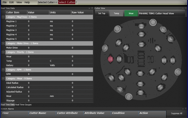
Sample screenshot of the Robbins remote cutter monitoring systems. Failed cutters are highlighted by a color on the screen.
Robbins Atmospheric Cutter Change System (RACCS)
Finally, we are developing a system to allow cutter changes at atmospheric pressure on large diameter EPBs. This atmospheric cutter change system is superior to other systems on the market because it allows muck to flow through. Other systems on the market are very prone to clogging. Each spoke of an EPB cutterhead will contain a chamber at atmospheric pressure. Cutters can be rotated from the pressure zone into the chamber to allow for efficient and relatively fast cutter changes.
The development is also significant because a huge cost of operating large diameter EPBs is associated with intervention for cutter inspection and change. We are currently building a large test fixture for this system, which will analyze how RACCS reacts in sand, gravel, boulders, clay, and mud conditions under pressure.
Conclusions
These research and development projects are all aimed at solving a particular problem or shortfall—with the objective to bore more meters per month. It is not the only area where we have research and development underway, as we have similar programs to investigate improvements of the probe drilling and lube systems on our TBMs. The process is usually rigorous, as designs need to be tested and re-tested in both the lab and the field.
I am not a big believer in “Big Step” research and development as was tried in earlier days at Robbins with the Mobile Miner and the Bore Pack. Such “Big Step” research and development usually leads to disappointment and heavy cost for the client and the company.
However, improvements like the 19” cutters and the cutter monitoring systems are and will be big wins for the contractors and for Robbins.
R & D is important in any industry, and it is no less true for the tunneling industry. Evolution, even if it is incremental, is where most research and development successes are made. Such improvement forms part of the competitiveness among manufacturers and thus begets further improvements. I also believe it is our obligation, as equipment manufacturers, to assist the market in driving down the costs of tunneling in general by improved product performance and product life.
Take, for example the research and development going on with our disc cutters: Robbins disc cutters have improved dramatically since the 1950s when they achieved their first success at 11 inches in diameter in crystalline limestone of 190 MPa (28,000 psi) UCS. Today’s disc cutters do reach 20 inches in diameter and cost-effectively excavate rock strengths of 400 MPa (60,000 psi) UCS, all while lasting much longer than their predecessors.
[Photo of a disc cutter]
That being said, we believe there is always room for improvement. We are working hard right now to develop customized cutters for EPB tunneling in soft and mixed ground, and to optimize those designs so they can excavate under high pressure. In hard rock, we are researching and testing new steels, and developing monitoring systems to allow contractors to plan cutter changes.
Here’s a snapshot of what research and development is going on in the cutter department, both in the lab and in the field:
Improved Metallurgy
Working with the University of Trondheim and the Norwegian government, we are commencing a program of laboratory and field testing to improve the materials making up the disc ring itself. We are always testing new materials in order to find the most durable materials based on the ground conditions. An example of past cutter research in the lab can be seen below:
Pressure Compensated Disc Cutters
We are currently developing improved disc cutters specifically for use on EPB and Slurry TBMs at high pressures of plus 10 bars, using a testing module in our Kent, Washington facility. The module duplicates a pressurized operational environment so that we can analyze how the cutter seals perform under pressure—the design is in its 3rd or 4th generation with continuous improvements being made. [Photo of testing facility?]
Remote Cutter Monitoring
Our remote cutter monitoring system is a breakthrough that we have been field testing for four years. The system is now undergoing full scale testing on three Main Beam TBMs at Malaysia’s Pahang Selangor Raw Water Tunnel. The setup allows crews to more closely monitor the actual working conditions and cutter wear. We project, through this system, to increase the TBM utilization of each machine by 3 to 4% and to reduce cutter cost by 10%.
We’re also working on expanding this wireless system to EPB and Slurry machines, so that monitoring of cutter wear and rotation can be used while those machines are in closed mode. This would be a highly beneficial development, because under pressure the detection of tool wear is difficult. Our goal here is to reduce or better plan interventions because of tool wear.
[Show screen shot of monitoring system]
Robbins Atmospheric Cutter Change System (RACCS)
Finally, we are developing a system to allow cutter changes at atmospheric pressure on large diameter EPBs. This atmospheric cutter change system is superior to other systems on the market because it allows muck to flow through. Other systems on the market are very prone to clogging. Each spoke of an EPB cutterhead will contain a chamber at atmospheric pressure. Cutters can be rotated from the pressure zone into the chamber to allow for efficient and relatively fast cutter changes.
The development is also significant because a huge cost of operating large diameter EPBs is associated with intervention for cutter inspection and change. We are currently building a large test fixture for this system, which will analyze how RACCS reacts in sand, gravel, boulders, clay, and mud conditions under pressure.
Conclusions
These research and development projects are all aimed at solving a particular problem or shortfall—with the objective to bore more meters per month. It is not the only area where we have research and development underway, as we have similar programs to investigate improvements of the probe drilling and lube systems on our TBMs. The process is usually rigorous, as designs need to be tested and re-tested in both the lab and the field.
I am not a big believer in “Big Step” research and development as was tried in earlier days at Robbins with the Mobile Miner and the Bore Pack. Such “Big Step” research and development usually leads to disappointment and heavy cost for the client and the company.
However, improvements like the 19” cutters and the cutter monitoring systems are and will be big wins for the contractors and for Robbins.
Sub-Sea TBM Tunneling: A New Approach to Oil and Gas Production
Offshore oil production is an important sector of business worldwide, but recent events have highlighted its inherent risks. We have witnessed catastrophic accidents on offshore drilling platforms that damaged the delicate marine environment and hurt businesses and families. Inclement weather and technological unreliability compound the problems that come with accessing oil fields in deep water.
Making offshore oil drilling as safe as possible is a high priority task—and one that could be advanced through TBM tunneling. Building oil production facilities in controlled environments underground has the potential to take at least some of the variables out of the equation. The tunnels would provide human access to the well head in deep water, and could be monitored for leaks and other malfunctions.
Extensive sub-sea tunnels for this purpose are being investigated in Norway, where schematics were drawn up for tunnel access to offshore oil fields in the early 1980s. Personnel access, transportation of drilling equipment, exploration and drilling for oil, and eventual piping of oil to the shore are all performed in tunnels and caverns underground. This enables access to the drilling sites and intervention by humans, rather than by remotely controlled and operated machines thousands of feet below water. Some concepts, such as the one below, feature a triple cross section—one tunnel would be used for materials transport, one is used for transport of personnel, and the third would be used as the oil supply pipeline.
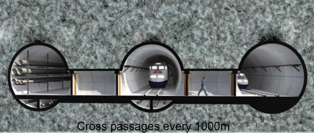
Schematic of triple cross section of concept subsea tunnel, courtesy of the Norwegian Tunnelling Society (NFF)
More than 40 subsea tunnels have been completed in Norway since their excavation was first proposed: 25 road tunnels, 8 oil pipeline tunnels, and 8 water supply tunnels. All of these tunnels were excavated by conventional drill & blast methods (D&B). The longest tunnel was 7.9 km (4.9 mi) (Bømlafjord), and the deepest is 287 m (942 ft) below sea level (Eiksund). Most of the tunnels were excavated in hard gneiss rock, with a few in shale and sandstone.
The slow relative excavation rates of drill and blast excavation, however, make this method of excavation on long sub-sea tunnels impracticable. Many new underground oil fields up for development will require long subsea tunnels of up to 50 km (31 mi) in length. These long tunnels must be excavated in the shortest possible time and as inexpensively as possible to make economical sense. At these tunnel lengths, mechanical full-face tunneling is the most realistic option. TBM technology for seabed excavation has been used on multiple projects since the 1980s, from the Channel Tunnel to the Boston Harbor Outfall and multiple tunnels worldwide.
New tunnels, as in the schematic below, would be built far below the sea bed, out of unstable regions that might experience sea water infiltration.
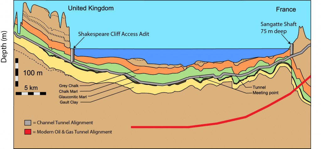
Schematic showing the depth of a modern oil and gas tunnel, compared to the depth of the Channel Tunnel.
In addition TBM tunneling would control the amount of over-break compared to drill and blast, by limiting the amount of material removed from the tunnel.
With today’s experience and know-how it is possible to excavate long tunnels under the sea in good time and with reasonable cost. The technology exists to improve oil and natural gas production from offshore oil fields, all that remains is for the method to gain acceptance in the industry.
Hybrid TBMs: A Clear Solution for Mixed Ground
It has been argued that the majority of good ground for tunneling in the world already has a tunnel going through it. While this might be an overstatement, it is true that more and more of today’s tunneling projects are being proposed in difficult, mixed ground conditions. Hybrid TBMs, specifically EPB/Slurry and EPB/Hard Rock machines, are increasingly becoming the best solution for these challenging conditions.
Hybrid machines have the potential to lower risk and make difficult excavations possible, as long as accurate geologic information is available. For example, a hybrid EPB/Open-Type machine can be optimized towards either end of the scale—depending on whether the majority of the drive is in soft soils or majority in hard rock—to produce the fastest possible advance rate over the entire project. If the tunnel is 80% soft ground and 20% hard rock, the overall machine design will be optimized towards EPB.
But what happens when the divisions are not so clear cut, or when the geology is 50% rock and 50% soft ground? A real example is the upcoming Sleemanabad Carrier Canal project, which will utilize a 10.0 m (32.8 ft) diameter Hybrid EPB/Hard Rock TBM. The 12 km (7.5 mi) long water transfer tunnel in Madhya Pradesh, India consists of shorts sections of hard rock and soft ground. Geology includes clay, gravel, marble, and hard rock up to 180 MPa (26,000 psi) UCS.
The solution at Sleemanabad is to provide three modes of tunneling: pressurized EPB tunneling, non-pressurized EPB tunneling, and open hard rock tunneling. The first half of the tunnel will be excavated using a specially designed screw conveyor, which can operate well in both the pressurized and non-pressurized environments. The oversized screw can be rotated faster to handle short sections of hard rock while minimizing any loss in efficiency.
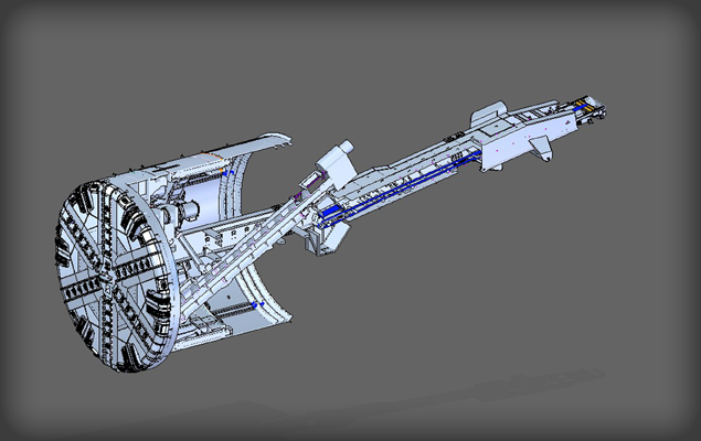
The 10.0 m (32.8 ft) diameter Hybrid EPB/Open-Type TBM for the Sleemanabad tunnel. The screw conveyor can be switched out with the TBM belt conveyor.
When a longer section of rock is encountered, the screw conveyor is removed and switched out for the TBM belt conveyor. Additional welded steel is added to the cutterhead to close up the open soft ground design, and the machine operates as a Single Shield TBM.
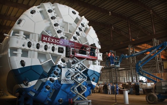
The mixed ground cutterhead supplied for one of three Robbins EPBs that will excavate Mexico’s Emisor Oriente tunnels is nearly identical to the one designed for the Sleemanabad tunnel.
In other conditions, such as sections of soft ground and rock mixed with sections of high water content, a Hybrid Slurry/EPB Type machine is desirable. The machines can similarly be optimized towards slurry or EPB depending on the amount of groundwater expected. An interesting example of this type of hybridization took place at the South Central Hillsborough Intertie Tunnel in Tampa Bay, Florida, USA. The machine excavated limestone with significant groundwater using both a screw conveyor and modified slurry removal system. See the case study here.
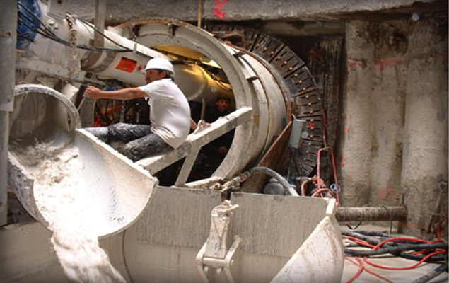
The Robbins hybrid EPB/Slurry machine at Tampa Bay utilized both a screw conveyor and modified slurry muck removal.
Hybrid machines are becoming more common, and are likely to gain in popularity over the near future. With greater experience will also come greater optimization of conversion times between modes—one of the biggest challenges during tunneling. While these machines do have some negatives, as all machine types do, the solution of Hybrid TBMs in mixed ground vastly outweighs any difficulties over the life of the project.
Ground Control: Mitigating the Inherent Risks of Urban Tunneling
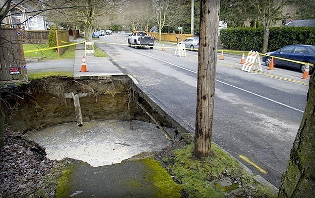
Sinkholes, as seen here at the Brightwater Conveyance Tunnels, can be an unfortunate end result of settlement. Photo Credit: TunnelTalk.com
Settlement. It is one of the biggest risks in urban tunneling and the cause of sinkholes, cracked building foundations, and tunnel collapses. Surface subsidence and upheaval have vexed contractors and equipment suppliers worldwide, but there are some proven ways to minimize ground movement, even in low cover tunnels.
Tunneling at Mexico City Metro’s Line 12 provides a good, recent example of settlement prevention. The 7.7 km (4.8 mi) route is being excavated just 7.5 to 14 m (25 to 45 ft) below downtown Mexico City. The 10.2 m (33.5 ft) diameter Robbins EPB is surfacing into eight cut and cover station sites during excavation, all along major downtown streets.
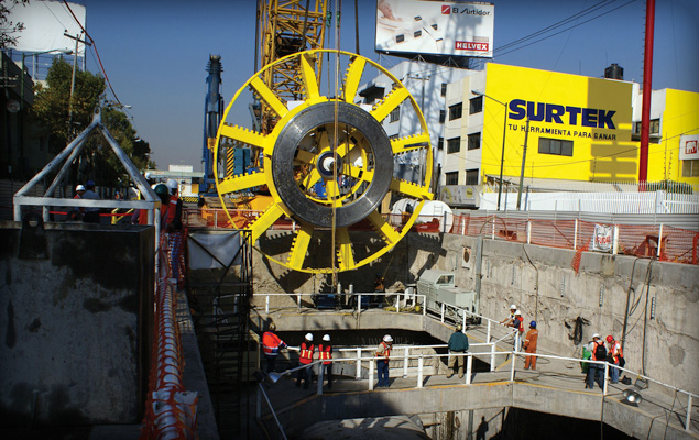
The Robbins EPB is boring just 7.5 to 14 m (25 to 45 ft) below city streets. Photo Credit: Yazmin Reyes
The ground, which consists of watery clays, sand, and large boulders up to 800 mm (2.5 ft) in diameter, makes settlement a concern. Ismail Benamar, Tunnel Manager for contractor Ingenieros Civiles Asociados (ICA), spoke about the measures they are taking to control the ground: “We have an extensive monitoring program to detect displacements and pore pressure on the surface, underground, inside the tunnel, and in the most critical structures next to the tunneling line.” The risk of surface subsidence and vibration is also being controlled by regulating the rate of advance and controlling earth pressure at the front of the machine, as well as the back-fill grouting pressure.
In particularly low cover areas, Benamar cited a reduction in EPB cutterhead rotation as one of the primary means of avoiding ground disturbance. Cutterhead rotation is kept low (around 1.5 RPM) while torque is kept relatively high.
In addition, the machine’s two-component back-filling system is used to further stabilize the space between concrete segments and bored tunnel. The liquid mixture consists of water and bentonite cement plus an accelerant, which are combined in the tail shield and harden rapidly after injection. Because the two liquids are kept separate, high pressure concrete pumps, which can disrupt the surrounding geology, are not needed.
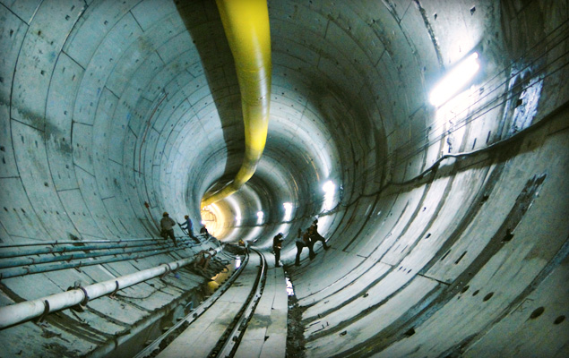
The Robbins EPB is utilizing two-component back-filling behind segments as one way of minimizing settlement. Photo Credit: Yazmin Reyes
By May 21, 2010, the machine had broken through into Mexicaltzingo Station—the first of eight cut and cover station sites along the tunnel route. Little to no settlement issues were recorded during tunneling.
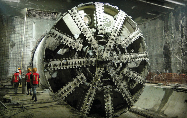
The Robbins EPB broke through into an intermediate station in May 2010. Photo Credit: Yazmin Reyes
Taken together, the methods at Mexico City Metro show the best ways to minimize settlement in urban EPB tunneling. Settlement can be due to multiple factors, including over-excavation, improper ground conditioning, inadequate back-filling, or loss of face pressure. Despite the risks, proper machine design, continuous monitoring, and a knowledgeable crew can keep ground under control.
For more about the causes of settlement and tunnel collapse, visit an online forum at tunneltalk.com
Multiple Machines: The Challenges and Successes of Delivering Three TBMs for Malaysia’s Longest Water Tunnel
Simultaneous delivery of TBMs, some of the most complex machines in the construction industry, is no easy task. Robbins TBM assembly is most often a local process—one that requires skilled workers with knowledge of components designed and manufactured all over the world.
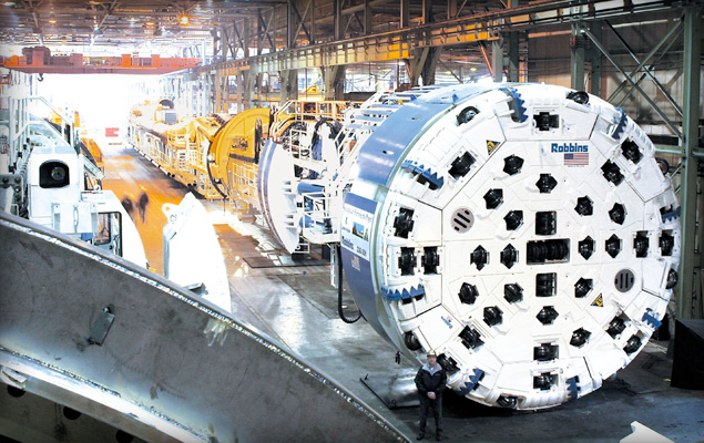
Robbins Main Beam TBMs assembled in the U.S. manufacturing facility.
Robbins use of local or nearby shops can often cut down on delivery times. A partial video of the TBM assembly process in the Robbins China-Shanghai facility is available here:
The video depicts the recent assembly of one of three 5.2 m (17.2 ft) diameter Robbins Main Beam TBMs. The machines are being built simultaneously for Malaysia’s Pahang Selangor Raw Water Tunnels, and are a good example of the assembly process.
Each machine is built at a workshop in Shanghai from components manufactured in the U.S. and China. After assembly of each machine is complete, the TBM and continuous conveyor system are shipped from Shanghai to Port Kelang in Malaysia. Once at the port, the components are trucked to the jobsite.
“One of the most difficult processes is finding a single shop that can manage the volume of fabrications and machining. The delivery times for the Malaysian TBMs are one month apart, which means that at one point you are disassembling and shipping the first machine, testing the second machine and starting assembly of the third machine,” said Kolenich. On average, each TBM requires a skilled crew of 20-30 fabricators, welders, and technicians, but shorter delivery schedules can require up to 60 people in two shifts. “We have an experienced group in China that has been building machines for many years,” he added.
Assembly of TBM #3, the first machine to be built, was completed in early July 2010. Assembly of the machine began with core components, including the main bearing and back-up structures, and finished with installation of the electrical and hydraulics systems, as well as outer components including cutterhead pieces and ground support.
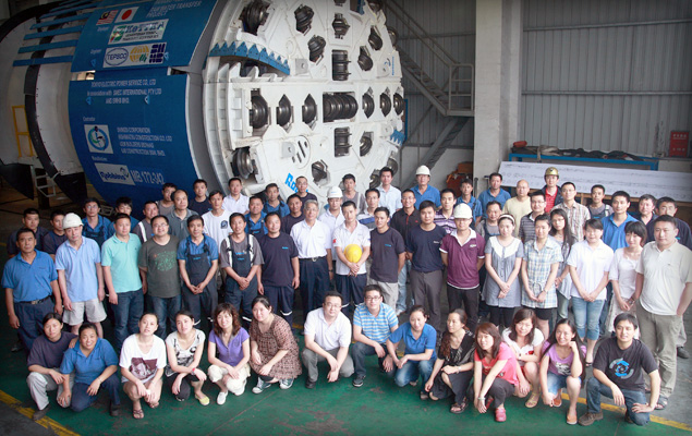
The first of three Robbins Main Beam TBMs was completed in July 2010.
“We perform all of the same quality inspections in our shops, regardless of location,” adds Kolenich. “At the end of assembly there is a two to three week no-load testing period to ensure that each machine is set up and functioning properly per the contractual and engineering requirements.”
The two other Robbins Main Beams will be completed later in 2010, with the factory acceptance for TBM #1 scheduled in August and TBM #2 in mid-September. The three machines will be launched between December of 2010 and March 2011.
For more about the Pahang Selangor Raw Water Transfer tunnels, visit the Malaysian Government’s Ministry of Energy, Green Technology, and Water.
View a short video about the project here:
Ground Support for High Cover Tunnels: What is the Best Method?
Conditions in high cover tunnels are often challenging. At the Olmos Trans-Andean tunnel, crews face 2,000 m (6,500 ft) of hard quartz porphyry, andesite, and other volcanic rocks under high stress. At two rail tunnels in China’s Gansu Province, open-type machines are boring beneath 1,400 m (4600 ft) of weak phyllite and sandstone.
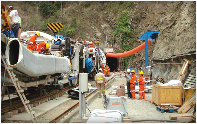
Launch of the Robbins TBM at Peru’s Olmos project, the world’s second deepest tunnel
Ground support, particularly in deep tunnel projects, is a highly debated topic. However, recent successes have pointed to several systems that work in a variety of situations. The Robbins Main Beam at Olmos was launched in 2007, and began to experience significant rock bursting and cathedralling under sections of high cover. “We encountered a 1,200 m (4,000 ft) section of highly fractured ground, with over 8,500 recorded rock bursts. Cavities also formed during tunneling that had to be injected with grout,” said John Simm, Robbins Field Service Superintendent.
To better contain the fractured rock, the machine’s roof shield fingers were removed and replaced with the McNally Support System, supplied by C&M McNally Engineering of Toronto, Ontario, Canada. The McNally support System provides the benefit of continuous support along the roof area of the tunnel, which protects workers from falling rock. The system works by replacing the curved finger shield plate for a curved assembly of pockets with rectangular cross-sections. Steel or wood slats are extruded from the pockets and bolted to the tunnel crown using a steel strap, effectively supporting and minimizing collapsing ground. As the machine advances, slats are reloaded into the pockets.
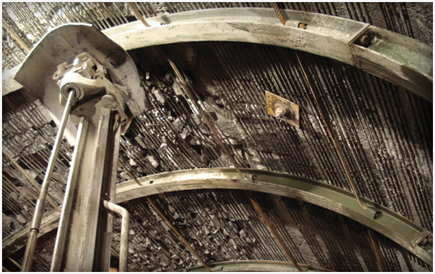
McNally slats supporting rock in the Olmos Trans-Andean Tunnel
The below video shows the crew loading McNally slats into the pockets:
The system successfully contained numerous high-pressure rock bursts at Olmos, as seen in the below video courtesy of Dean Brox from Hatch Mott MacDonald:
For the machines at China’s West Qinling tunnels, the answer is a versatile ground support system that can be adapted depending on the ground conditions. The two 10.2 m (33.5 ft) diameter Main Beam TBMs are the first Robbins Main Beam machines built with specialized ground support and no finger shields. Instead of the roof fingers, the machines are designed with mesh pockets beneath a protective shield for workers to safely install mesh panels.
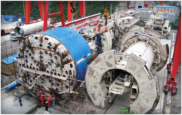
Assembly of two Robbins Main Beams with specialized ground support at China’s West Qinling Tunnels
The machines can also use the McNally Support System if needed. Modified pockets can be bolted inside the mesh windows, allowing space for short slats of steel or wood.
In addition, streamlined materials handling and separate roof and probe drills allow for improved progress in high cover conditions. Redesigned ring beam installers allow for loose assembly and expansion against the tunnel walls, and can be easily converted to install steel straps rather than full rings.
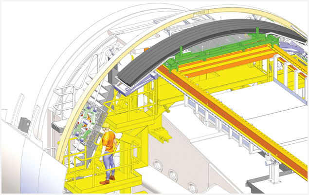
Materials including ring beams and mesh panels are transported on a remotely operated carriage, requiring fewer transfer points
Both machines are currently excavating 16.6 km (10.3 mi) long rail tunnels.
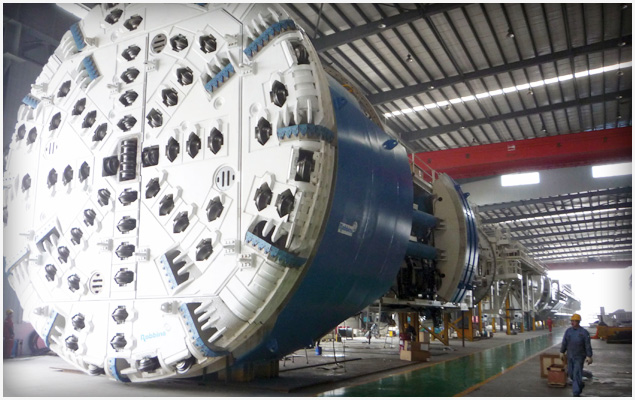
The two 10.2 m (33.5 ft) TBMs were launched in June and July 2010
For more information on ground support in large diameter tunnels, check out this recent technical paper: Large Diameter TBMs_WTC2010
Recent Posts
- Tunneling in Turkey: The Esme Salihli Railway
- Incredible India: Machines on the Move in Agra and Delhi
- Notice of Retraction and Apology
- Four Things You Need to Know about Probe Drilling and Pre-Grouting
- The Latest Updates: Records in Toronto, the News from Nepal, and More

 Close
Close  Menu
Menu 


